Home About us Contact us Protuner Loop Analyser & Tuner Educational PDFs Loop Signatures Case Histories
Michael Brown Control Engineering CC
Practical Process Control Training & Loop Optimisation
Control Loop Case History122
Foreword by Michael Brown
This is the second contribution in this two part series by Etienne Wannenberg, who applied some of the teachings in my Part 2 Course on Control of More Difficult Processes, and has written an excellent article on his work.
Part 2: Controlling Swell and Shrink in Boiler Drum Levels
Introduction
Steam drum level is one of the major contributors of boiler trips and downtime. Effected with a specific phenomenon (swell and shrink) it is difficult to optimally control the drum level.
Babcock conducted studies to determine the best control configuration to control steam drum level and how to optimise it. In the previous edition of SA Control and Instrumentation, the single and two-element control configurations were explained and tested. The basic configuration and test results of the three-element control will be described in this article.
Boiler Process
To reiterate the main topics mentioned in the previous article;
In natural circulation boilers the steam drum is used to separate the steam from the water by using mechanical equipment (scrubbers and cyclones). The steam drum can be seen as the balance point of the boiler.
The steam flow from the boiler is controlled by the downstream process demand. A sudden increase or decrease in steam flow changes the pressure in the steam drum and boiler circuit. The change in pressure will cause a change in both the boiling point and density of the water and steam. These combined reactions will cause the level in the steam drum to rapidly increase/decrease. This phenomenon is commonly known as swell and shrink.
The swell and shrink reaction will be in the opposite direction to the normal behaviour of the boiler process. Thus, swell and shrink reactions adversely affects the controllability of the steam drum level.
Drum level control is designed to maintain the drum level at 50% of the capacity. It was indicated in the previous article that two-element configuration is superior to the single-element in that it reduced both the settling time and reaction magnitude.
The testing was conducted on two identical 55 t/h Babcock boilers connected to a common header which supplies steam at 66 Barg 490°C to a single turbine unit.
Boiler 1 was used as the baseline for the testing. The steam drum level configuration on boiler 1 was left on single-element control during the test period and compared to boiler 2 three-element control configuration.
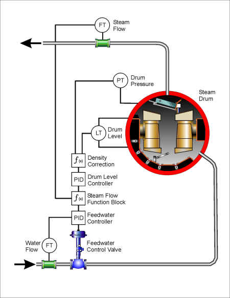
Three-element control
The three-element configuration is formed by cascading the drum level and feed water controllers with the addition of steam flow feed forward signal. The steam flow signal is added to the drum level controllers output. Figure 1 indicates the basic three-element configuration.
Figure 1
The principle of the three-element configuration is to control the mass balance of the steam drum. If steam is removed from the boiler circuit, the loss of steam must be replaced with an equal mass of feed water.
The feed water and steam mass balance cannot be used independently to the drum level controller. It is especially difficult to obtain a precise measurement of steam mass flow due to the allowable reference accuracy effects of the physical measuring instrumentation. Furthermore, the boiler is normally not a closed circuit. Steam drum blow down and sootblower steam take off will affect the boiler mass balance. Thus, the drum level control is retained in the configuration to resolve the problems experienced by the mass balance control and will be used as a trim function.
A function block is used to introduce the steam flow signal to the drum level controllers output. The function block is used to manipulate the steam flow signal. A steam flow influence magnitude adjustment is used to change the controller from two to three-element control. When the value is adjusted to 100% the full magnitude of the steam flow will be used in the control loop.
The function block furthermore contains a drum level controller bias signal. The bias signal is used to correct the operating range of the drum level controller’s output. At steady state condition the steam flow will equal the water flow. If this mass balance maintains the drum level at 50%, the output of the drum level controller will be reduced to zero. Operating the drum level controller output close to zero is not ideal.
The bias signal will correct the drum level output signal to operate close to 50% under steady state conditions. The value of the bias signal is dependent on the specific boiler process and can only be obtained with testing.
Switching from Two-element to Three-element control
Unlike the single and two-element configurations, three-element cannot be used from start-up conditions due to the steam flow being unreliable.
When sufficient steam pressure is achieved during start-up and a reliable main steam flow is maintained, the drum level control can be switched to three-element control.
The three-element configuration utilises the same controller used in the two-element configuration. Retuning of the controller is thus not required. The steam flow signal influence magnitude is only increased until the full signal is used.
During this increase the drum level output signal will reduce as the steam flow signal is increased. The bias signal must be adjusted in proportion to the steam flow signal to maintain the correct drum level output signal.
The steam drum mass balance requires the water flow and steam flow to be equal, thus no gain is placed on the steam flow signal. The raw value derived from the process is used directly in the control configuration.
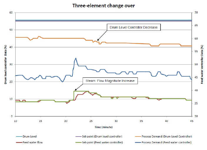
Figure 2 indicates 10% increase in the steam flow magnitude signal. It is indicated that the set-point of the feed water controller is increased without an increase in the drum level controllers output. The feed water flow is increased due to the change in set-point of the feed water controller, which is followed by a decrease in the drum level controller output.
Figure 2
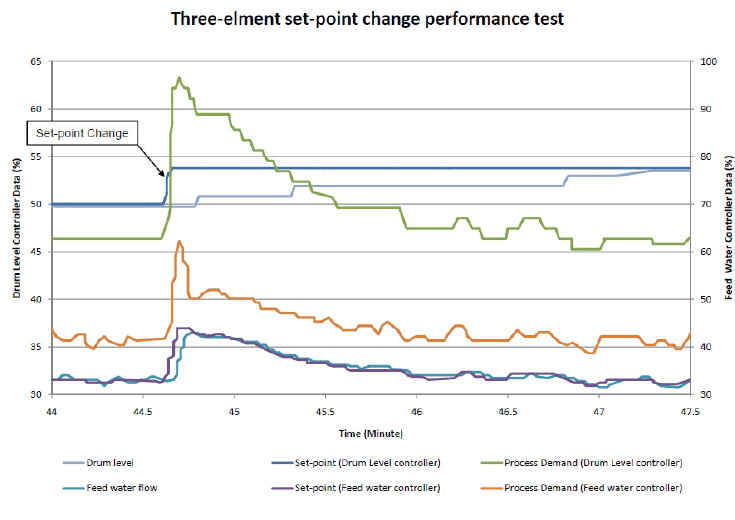
Three-element performance test
During the implementation period of the three-element controller, set-point changes were introduced to establish the configurations performance. Figure 3 indicates the set-point change test result where the drum level set-point was increased from 50% to 55%.
At the instant of the test, the magnitude influence signal from the steam flow was maintained at 40%. The set-point test indicated that the controllability of the configuration did not deteriorate by the addition of the steam flow signal.
Figure 3
A steam demand reduction was experienced during the implementation stage of the three-element controller. The common turbine supplied by the two boilers, tripped. The trip was caused by a turbine fault which retained the boilers to remain in service.
During a turbine trip the steam supply valve is closed and the turbine by-pass line is opened. The turbine supply valve closes quicker than the by-pass valve can open. Thus during the change from turbine to by-pass the steam flow is momentarily stopped.
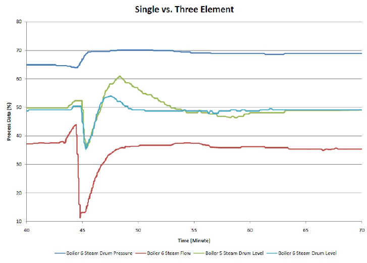
Figure 4 indicates the reaction load change on both the drum levels due to the turbine trip. The steam drum pressure and steam flow for boiler 2 is also indicated.
Figure 4
The changeover to three-element control was not completed at the time of the turbine trip. The steam flow influence signal was set at 70 %. Even without the complete steam flow signal the load change indicated an improved performance compared to the single-element control.
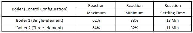
Table 1 summarises the reaction recordings.
Table 1: Summary Table
The recording indicated that the load change was more severe than compared to the previous article. The drum level experienced a dramatic shrink function. Both boilers activated the low drum level alarm. After the shrink function, boiler 1 overshot the set-point significantly more than boiler 2.
The three-element control on boiler 2 also stabilized 7 min faster than the single-element control on boiler 1.
Conclusion
The testing identified that the three-element control configuration is superior compared to the single-element configuration. The load change confirmed that the three-element control configuration experienced the same initial shrink function as boiler 1 but improved the reaction magnitude and settling time after the shrink function.
The configuration of the three-element control was not designed to cure the shrink and swell reaction. As indicated above the addition of the steam flow signal will drive the control valve to close during a shrink reaction. This is directly opposite to maintaining the drum level at set-point during the shrink reaction.
However the closing of the valve is required to stabilise the process after the shrink reaction. Thus the addition of the steam flow signal improves the control only after the shrink function and will not obviate the shrink or swell reaction
The testing of the configuration had to be concluded before a solution was found for the shrink/swell function. Further development of the configurations will be continued when a similar opportunity arises.
To summarise:
The single-element control functioned relatively well and has a simple construction; however it offers the worst performance of the three configurations.
The two-element control offers improved performance compared to the single-element and is relatively simple to install. On most boiler plants only the addition of the cascade control and retuning of the loop is required to obtain two-element control. The addition of the cascade controller will also mitigate valve problems to large extent.
The three-element offers the best performance of the tested configurations. The configuration is the most complicated but is simple to derive from the two-element control. Engineering consideration is however required during implementation and start-up activation.