Home About us Contact us Protuner Loop Analyser & Tuner Educational PDFs Loop Signatures Case Histories
Michael Brown Control Engineering CC
Practical Process Control Training & Loop Optimisation
CONTROL LOOP CASE HISTORY 152
CONTROL PROBLEMS WITH AIRFLOWS IN FLOTATION BANKS
I have written quite a few articles specifically dealing with control problems in mineral processing plants which are largely due to poor understanding and apparently complete lack of concern of control practice by the plant designers. As a general rule the control systems in these types of plants perform very badly. Apart from the lack of knowledge, the control equipment used in these plants is often purchased with price as the chief criterion, and little thought is taken as to the long term effects of poor control on profitability of the plants.
To offer a very simplified description of the process: Flotation banks are used to separate the desired minerals from other constituents in a slurry. To achieve this the slurry is treated with certain additives and passed through a series of tanks. Air is bubbled through each tank from the bottom forming a “bubbly” froth on top of the slurry. The desired minerals adhere to the bubbles and the “rich” froth overflows the top of the tank. The remaining liquid below the froth gravitates to the next tank where the process is repeated. The three main controls in each tank are pH, liquid level, and airflow. The last two are particularly critical for good recovery.
In earlier days the level was regarded as the most important. However in recent years the metallurgists have realised that the airflow is also very important and it is becoming common for online froth analysers to be used to control the airflow.
In the course of my career I have performed optimisation in many of these plants, and of all the controls I have ever come across the airflow controls are probably the ones that seldom work. This at first sight seems strange as probably flow is the easiest of all processes to control. Even without a scientific tuning package flow is relatively easy to tune as it has fast response, and one generally finds most flow control loops in plants are working in automatic, even though they are generally not working efficiently in most plants. (The reason for this is of course that very few people know how to analyse loop problems and tune the loops properly.)
Why then do the airflow loops on flotation plants seldom operate correctly? The two main general reasons for this are the poor measuring transmitters and control valves which are very often installed in these plants. Firstly the plant suppliers generally go for a make of cheap and literally nasty thermal flow meters, which suffer badly from drift and are not at all accurate. They also often seem to stop working properly at high ambient temperatures and give false readings.
Secondly the suppliers install very low cost and really bad valves with positioners and actuators that are not good for modulating control systems.
What is quite interesting is that the majority of flotation plant personnel including the metallurgists nearly always tell me that their flow controls are working perfectly, when in fact they are really not working at all. Why is that? The reason is that not many plants are yet using the airflow controls cascaded down from froth bubble analysis. The operators put the controllers into manual and get the flow to where they want, and then put the controllers back into automatic, and the flow stays where it is as nothing changes. This makes great trends. The flow on setpoint! Great control! We call these trends “tramlines".
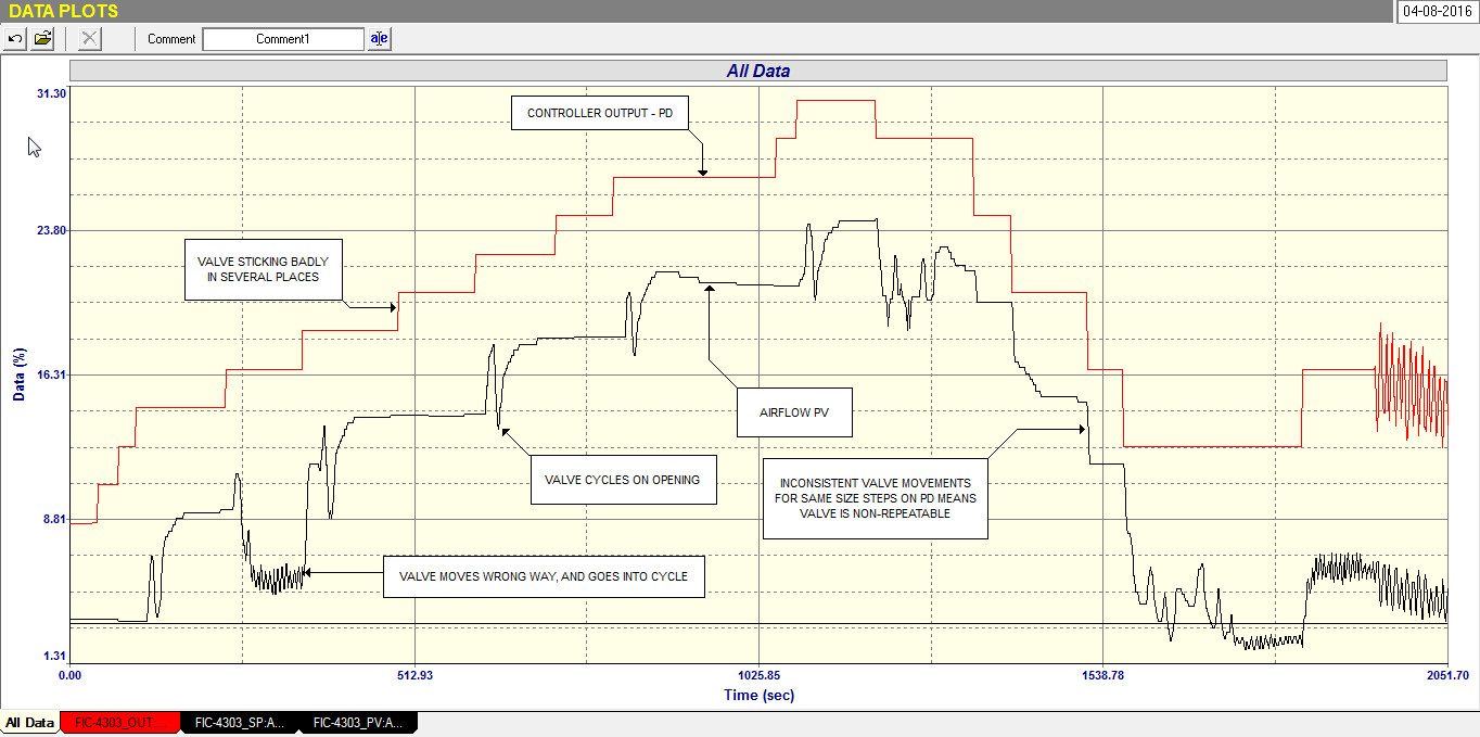
I was recently working on flotation bank control at a mine in Portugal where again they were convinced that the airflow controls were working splendidly, but they will be using higher level control soon, and wanted to check how good the controls really are. Figure 1 is the recording taken from an open loop test on one of the air flow control loops, and shows just how terrible the valve was. It can be seen that it is not doing what the controller is asking. The controller was in manual and equal steps are being made on the way up, although larger steps (equal in size) are being done on the way down. The valve sticks at times. It sometimes overshoots and cycles. On one occasion it even moves in the wrong direction. On occasion the valve responds with differing size steps for the same size steps on the controller output. All of these things mean that the valve is non-repeatable and does not do what the controller is asking. There is no way that any reasonable automatic control could be achieved with a valve like this.
Fig 1
To compound it every single valve of the many we tested on the banks was as bad, if not worse than this. This type of thing is really common on many of the float banks I have worked on. It makes one wonder why so much money is wasted on control, and even more so as it shows up how plant personnel have so little idea of what is going on with their controls.
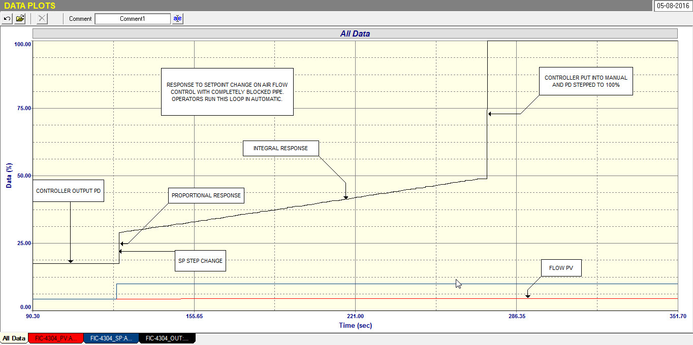
To illustrate again how people don’t seem to be aware of what is going on with their controls the second example is of airflow on a float cell, where everyone was quite happy that the control was fine. Figure 2 shows an open loop flow test. The Operators just set the setpoint at a particular value, and left it. Nobody could have checked anything for as can be seen in the test the valve was jammed solidly in one position and although the controller’s output was stroked from zero to 100%, the flow never moved, and was stuck at 4%. These things are hard to believe. Surely the cell’s performance must have been bad, but no one was worried about it.
Fig 2
I have often said that feedback control is “grey area”, of which few people have any real practical knowledge, and these examples illustrate what I mean.