Home About us Contact us Protuner Loop Analyser & Tuner Educational PDFs Loop Signatures Case Histories
Michael Brown Control Engineering CC
Practical Process Control Training & Loop Optimisation
CONTROL LOOP CASE HISTORY 158
REPORT ON TEMPERATURE CONTROL OF AUTOCLAVE
I was recently asked to help with a client who treats a product in an autoclave, and was complaining that they always got overshoot on the step setpoint change to holding temperature: The following is taken from my report:
The autoclave is a special case of what is often referred to as “Batch Temperature Control” where a load is placed inside a well insulated chamber, and the temperature setpoint is then stepped up to a desired holding or soaking temperature. The two main control requirements are normally:
- No overshoot is allowed, because as there is no cooling and the heat loss from the chamber is very small. Therefore if an overshoot has occurred, it will take an extremely long time for the temperature to drop back to setpoint, even although the control valve is fully closed.
- The PV must get to SP as quickly as possible to allow more production through the unit.
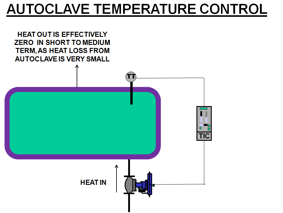
Refer to Figure 1. The heating of a unit like an autoclave is known as an “integrating”, or “ramping”, or “balancing” process, which is similar to control of level in a tank. The only time that the level in a tank can remain constant is when the inflow and outflow are equal. If the flows are not equal, the level will always be ramping up or down. Therefore the control requirement for a constant PV is to get the inflow and outflow to be equal, or “balanced”.
Figure1.
In the case of the autoclave we need to keep the heat inflow equal to the heat outflow for the temperature to remain constant. However the significant and really unique point of this type of process is that the heat flow output from the chamber is zero in the short to medium term. This means that to have a constant temperature the valve needs to be shut or very close to shut, otherwise the temperature will keep rising. Therefore the “trick” is to open the valve fully on the setpoint step change to heat the vessel as quickly as possible, and then to keep it fully open until there is exactly sufficient heat energy in the vessel to get the temperature to setpoint. By then the valve should already have returned to the fully closed position, as the PV will still rise for a short while after the valve is closed.
Normally one uses proportional (the P term) plus integral (the I term) control on most processes. The only purpose of the I term is to ensure that the PV does get to SP without offset. However there is a problem when using the I term in the controller on an integrating process. This is because with the particular dynamics inherent to integrating processes if one uses the I term in the controller the PV will always overshoot the SP on SP step changes. Thus the I term cannot be used on the controller for this application as overshoot is not allowed.
Therefore one has to use a controller with the P term and no I term.
Please note that in certain batch temperature processes there is sometimes an additional dynamic which cause the PV to respond initially in a “lag” fashion on the SP change (it curves up into the ramp). In these cases it is essential to also use the derivative term (the D term) in the controller to cancel out the lag. However in the case of the autoclave under consideration the temperature starts ramping at a constant rate within a relatively short time after the SP step change has been used. Thus the D term will not help in this case.
We are therefore forced to use a P only controller.
To tune the controller is not as difficult as one might initially feel, because an interesting fact is that with an integrating process with effectively zero heat loss, even with a P only control the PV must at least always get to SP, and it cannot end up below SP. The reason for this is that with zero heat output from the unit, if the PV is less than the SP the output of the controller must be above zero. (Controller output = P gain x Error). Thus the valve will not be closed and heat will still keep inputting the unit and cause the temperature to continue to rise.
Therefore the only problem that we can encounter with P only control is that we may end up above setpoint (i.e. with an overshoot).
So essentially the trick in tuning such a process is to do tests with SP step changes starting with low P values, and increase the gain on each test until we get to SP in the shortest time without overshoot.
An important point with P only controllers is that because there is no I term, the controllers must have an adjustable bias, which allows one to move the PD (controller output) up or down manually by the bias value. (Most P only controllers default to an initial bias value of 50%.) However in this case the bias must be set at zero percent, so that the PD is at zero when the PV = SP. This ensures the valve is closed when the PV is at SP and there is zero error.
It is also very important with this control is to ensure that the valve calibration is correct so that it is fully shut at zero PD, and immediately starts opening when the PD moves up from zero. This is critical.
If the holding (soaking period) is very long there may be enough heat loss from the unit to cause the PV to start dropping when the valve is fully closed. Generally the P only term will be able to limit this drop as usually on units like autoclaves, as the tuning ends up with a pretty high P gain. However in certain cases people switch on the I term after the PV has reached the setpoint. This ensures the valve will definitely open enough to keep the PV at SP.
After implementing the recommendations my client kindly sent me the following screen shots which are actual trends captured from his SCADA, and which shows how well the P only control strategy worked:
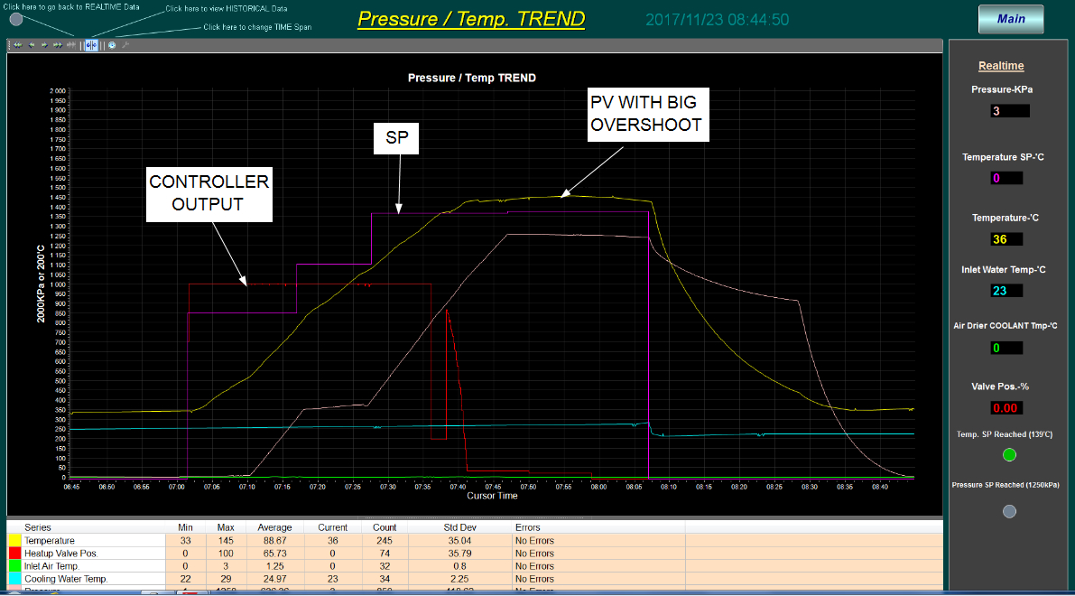
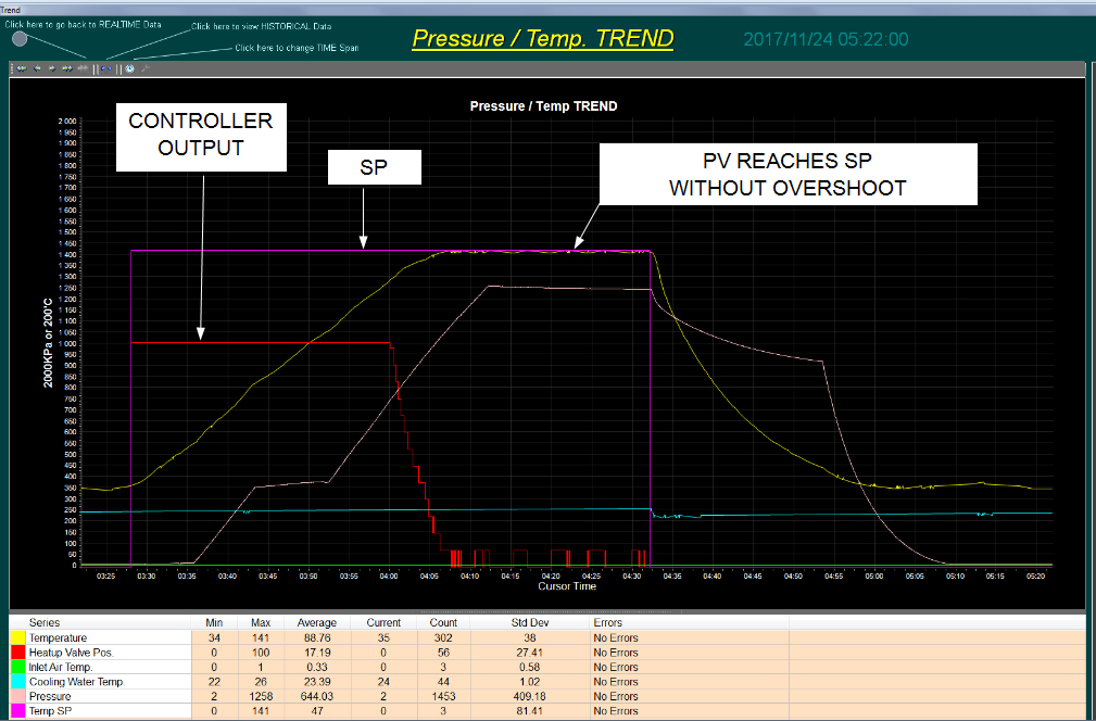
Figure 2 shows the response to a step change in setpoint with P+I control, and Figure 3 the response with properly tuned P only control.
Figure 2.
Figure3.