Home About us Contact us Training Optimisation Services Protuner Educational PDFs Loop Signatures Case Histories
Michael Brown Control Engineering CC
Practical Process Control Training & Loop Optimisation
CONTROL LOOP CASE HISTORY 160
MORE PROBLEMS WITH CONTROL
In a recent assignment to sort out problems being experienced in a petro-chemical refinery, I came across the following two examples.
The first one was with the control of an overheads drum pressure which was behaving badly. In particular the cascade secondary flow control from the pressure was in an unstable cycle and was interacting with other loops causing all sorts of problems.
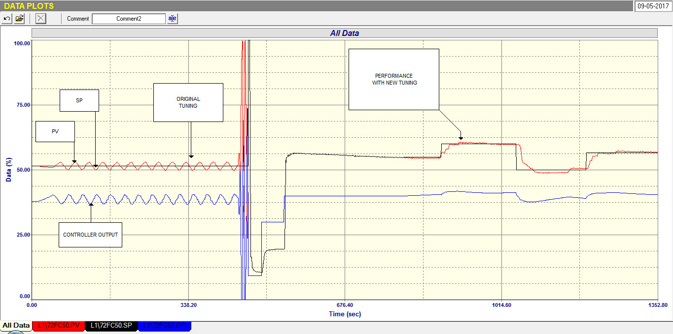
The flow loop was tested first. The tuning was very slow and it was found that a PV (process variable) filter with a time constant of 15 seconds had been used. This is a relatively huge filter for a flow loop and is definitely not recommended, particularly as one wants a cascade secondary loop to have really fast control, so that it does not interact with the primary loop. It was also seen that the loop was in a continuous unstable cycle when in automatic. This can be seen in the first part of the recording in Figure 1.
Figure1.
It should also be mentioned that loop was badly tuned with a Proportional gain of 1.0, and an Integral of 0.12 minutes/repeat.
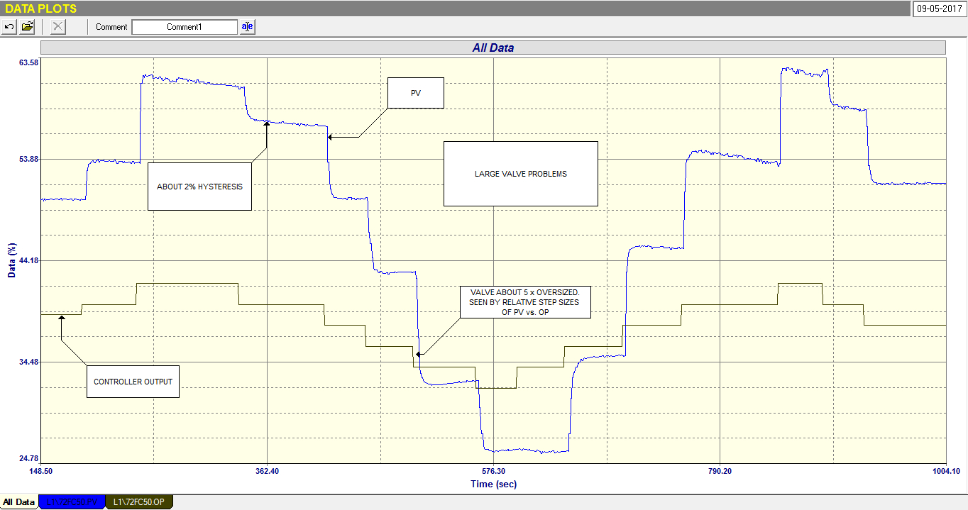
Figure 2.
Figure 2 shows the open loop analytical and tuning test, which was performed with the PV filter removed. It shows:
1. The valve is about 5 times oversized. This can be seen by the relative step sizes of PV and PD (controller output). An
oversized valve amplifies all the valve faults and cycling by the oversize factor, and such a large oversize is definitely not recommended.
2. The valve is suffering from about 2% hysteresis which when amplified by the oversize factor means that the control error is
being increased to about 10%. (As a general rule of thumb, valve hysteresis should not exceed 1%). A rough definition of hysteresis is the maximum offset experienced when a valve is moved from a particular position to another, and then commanded to return to the original position.
3. On many steps the valve overshoots and then is slowly being brought back to the correct position by the valve positioner.
The valve’s performance is fairly repeatable even with such severe faults, which means that control of a flow loop which normally has relatively fast dynamics should be possible, although action could be taken when possible to repair or replace the valve. Therefore a new tuning was done which was designed to give a critically damped response to a step change on the PD, i.e. the fastest response to the step without overshoot. The reason for this is to minimise valve reversals, as each time the valve has to be reversed will necessitate the controller’s integral term having to ramp the output through the hysteresis band before the valve can start moving in the opposite direction, which can dramatically slow the control. The new tuning resulted in a Proportional gain of 0.05, and an Integral of 0.03 minutes/repeat.
The later part of the recording shown in Figure 1 shows how well the control worked with this tuning. Comparing the original and final tunings will clearly show why the loop was originally in a continuous unstable cycle.
An interesting fact is that control response is largely due to the product of Process Gain x Controller Gain. Therefore a 5 times oversized valve means that the Process Gain is about 5. Therefore the Controller Gain needs to be five times smaller than it would be if the Process Gain was unity if stable and robust response is to be attained!
Another interesting fact is that this is yet another example which shows how effective cascade control is in overcoming valve problems on processes with slow dynamics. In this case if the pressure controller had been directly connected to the valve and not via the flow loop, there is almost certainly no chance that any pressure control could have been obtained with the controller in automatic.
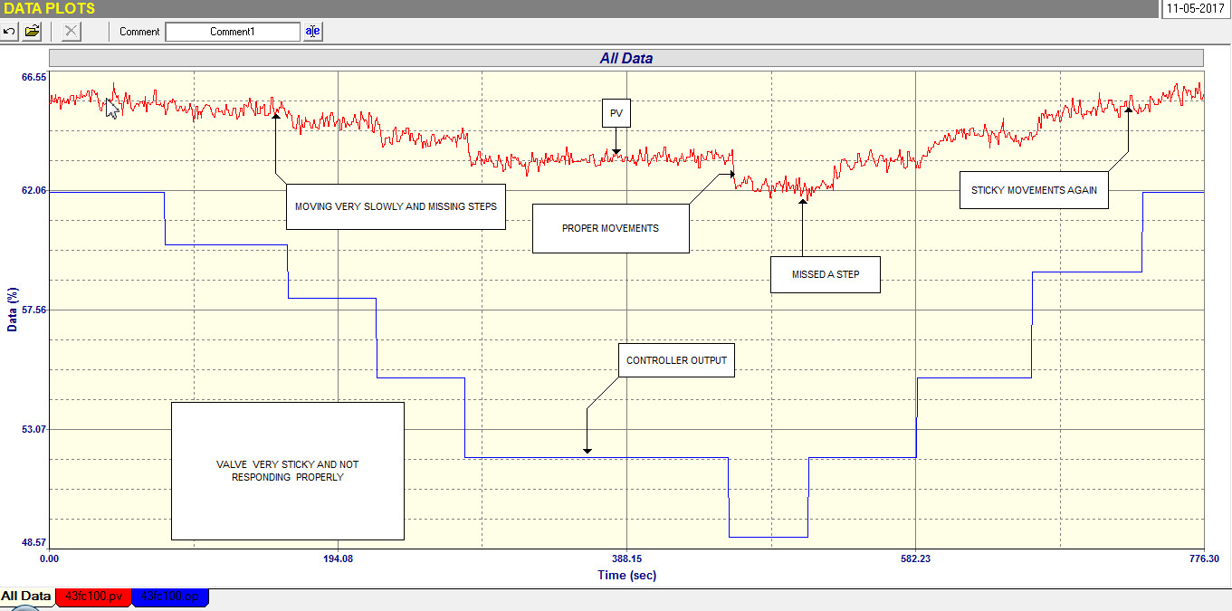
The second example here is of another flow loop which is cascaded from a level control. Again it was a loop that had been flagged as performing very badly by the operators. Figure 3 shows the open loop test.
Figure3.
The test shows very clearly how badly the valve was performing. It is extremely sticky particularly when closing, and sometimes missed steps altogether. There is no way that good flow control can be achieved with this valve.
Another point of interest is that the process gain appears to be very much smaller than unity. This is normally a sign that the transmitter span is far too wide, but if that was the case here then one would expect the PV signal to be near the low end of the scale, which it is not. This is definitely a case where the calibrations of both the valve and the transmitter need checking, apart from servicing the valve and getting it to respond properly.
Once again there is no way that they would have been able to control the level in automatic if the valve had been directly connected to the level controller’s output. It is really amazing what valve problems can be hidden and overcome when using cascade secondary flow controls on slower primary loops.