Home About us Contact us Protuner Loop Analyser & Tuner Educational PDFs Loop Signatures Case Histories
Michael Brown Control Engineering CC
Practical Process Control Training & Loop Optimisation
CONTROL LOOP CASE HISTORY 180
FUEL GAS PRESSURE CONTROL PROBLEM
I was asked to sort out a serious control problem on a fuel gas pressure control in a refinery some time ago. The loop in question was the cascade secondary loop to the furnace temperature control, and as such is an extremely important control as furnace temperature is of critical importance in a refinery process.
A cascade secondary control loop with temperature as the primary control usually has to work quite hard with fairly big movements, due to temperature processes being normally quite slow and requiring quite “hefty” tuning.
The problem with the pressure control was that it seemed to work intermittently, and sometimes was almost unstable. It also seldom got to setpoint. As a result they were getting large and unacceptable variance on the temperature control.
Testing was extremely difficult to perform on this loop as the operators were insistent that only very small changes could be made as downstream production could be badly affected if we moved things too much. For this reason we could not make all the steps I would like to have done.
Figure 1 shows the closed loop test “as found” which is a test performed with the loop on local setpoint and using the original tuning parameters. It shows two things quite clearly, firstly that the loop was almost unstable, and secondly that the response was slower as the setpoint was moved up, which could indicate non-linear installed valve characteristics.
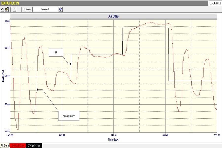
Figure 1.
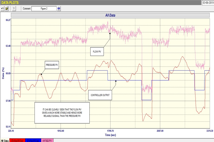
Further tests also showed that the pressure dynamics were “behaving” in a strange manner that was not reflective of the actual valve movement, with the pressure PV moving around quite considerably when the controller output was constant. It is not clear as to the cause of this, possibly it was a problem in the measurement, but certainly it would be very difficult to try and get reasonable and consistent control with that behaviour.
Figure 2.
Fortunately we discovered that there was a flow transmitter in the gas line and found that this gave a much better indication of the valve’s performance than the pressure. This is shown in Figure 2 which is of an open loop test, and the difference in the behaviour of the two PV’s can be seen. It was therefore recommended that the cascade secondary loop should be changed from the pressure to the flow.
Unfortunately in this plant, as in many others, one cannot just change things like a control strategy immediately. Changes have to be approved by a committee comprising process, and control and instrument engineers. Obviously the loop would have to be retuned if the change is made.
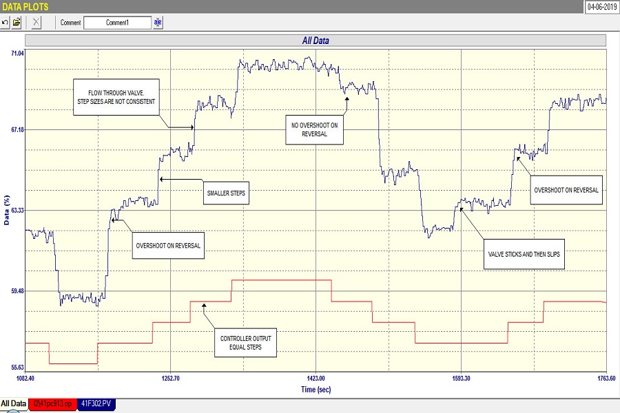
Figure 3.
Figure 3 shows an open loop test with the normal type of steps being made on the PD (controller output) and response of the flow PV being shown. The pressure PV was also recorded as it was needed to try and get a better tune to use in the meantime, but that trace has not been shown in the figure for the sake of clarity.
Figure 3 clearly shows that fairly severe valve problems also existed. These are:
1. The valve movement is very non-repeatable. It sometimes overshot on being reversed and at other times it stuck quite badly on a reversal.
2. Although the steps made on the PD were all of the same size, the valve seemed to move in smaller steps on opening, and much larger steps on closing.
3. At times the valve stuck for a while and then eventually slipped.
4. It looked like the installed valve linearity wasn’t too bad, but it is hard to be sure from this test. It certainly looked like non-linearity in the first “as found” closed loop test shown in Figure 1.
5. Comparing the magnitudes of the steps in PV versus those in the PD, the valve is probably 3 - 4 times oversized. As mentioned numerous times in past articles, oversized valves amplify all problems by the oversize factor.
It is almost impossible to get good control with such a valve. It was therefore recommended that the valve be serviced and preferably replaced with a correctly sized one.
Just in passing it is interesting to note that I did optimise the same loop some 11 years previously, and on comparing the then and present tests, it was seen that the process dynamics had changed completely. A subject of frequent discussion is how often one needs to reoptimise a control loop. This is very hard to answer in general as it depends on many different factors.
My own experience is that dynamics do change on most loops with time and varying process conditions, and this to me is an argument for the use of a continuous on-line loop performance monitoring package. These devices are often used in an effort to highlight badly performing loops, but I have found that these packages when used alone can detect some really bad loop problems, they often cannot show up many other faults, and are prone to misinterpreting certain types of loop performance. This can only be effectively done by individually analysing and optimising each loop. They really come into their own, AFTER the individual loops have been properly optimised, as they can immediately give warning of deterioration in loop performance.