Home About us Contact us Protuner Loop Analyser & Tuner Educational PDFs Loop Signatures Case Histories
Michael Brown Control Engineering CC
Practical Process Control Training & Loop Optimisation
CONTROL LOOP CASE HISTORY 182
A TEMPERATURE CASCADE CONTROL LOOP THAT DIDN’T WORK
The problems encountered in a heater outlet temperature control in a petrochemical refinery are discussed in this article. The control was causing considerable difficulties for the operators who complained that the control didn’t seem to work at all well, and they found it almost impossible to run it in manual. The outlet temperature affected the quality of a large number of downstream products and was considered of critical importance. The control consisted of a temperature–flow cascade system. In particular the temperature had extremely slow dynamics and took an exceedingly long time to fully respond to changes.
I am a great advocate of cascade systems when used on important control loops with slow dynamic responses. One of the major limitations of feedback control is that one can only tune the controller to give a response that is as fast as the dynamics of the process will allow. If one tries tuning it to react faster than that, cycling and possible instability will occur. This effectively means that one can control processes with fast dynamics quickly, and processes with slow dynamics slowly. The slower the dynamics, the slower has to be the tuning.
Therefore if you wish to control slow processes successfully it is extremely important that not only should the tuning be really spot-on, but it also becomes critical to eliminate any problems that can occur in the operation of the final control element. These problems could include many factors such as hysteresis, stick-slip, non-linear installed characteristics, and non-repeatability. If these things occur then the feedback controller will see the process is not getting to setpoint and will also have to overcome the problems caused by the equipment. However with the very slow tuning the controller can also only correct for the valve’s problems extremely slowly, and this can result in really dramatically poor control response. My best example of this was on a temperature control in a cement plant where the valve had 5% hysteresis. With good tuning it took the controller 7.5 hours for the PV (process variable) to settle out at SP (setpoint) after a 10% step change in SP. It took only 7 minutes once the valve was fixed!
As it is almost impossible to manufacture completely perfect final control elements, particularly pneumatically operated valves, then for processes with very slow dynamics one can install a secondary flow control loop around the valve, the SP of which is fed directly from the output of the temperature controller. The flow loop generally has extremely fast dynamics, and can respond to changes in only a very few seconds.
The temperature controller instead of just instructing a valve to move to a certain position, now effectively instructs the flow controller to feed the actual desired flow of product into the process to satisfy the control requirements. The flow controller with its relatively, almost “lightning fast” dynamics as compared with those of the temperature process, ensures the flow satisfies those requirements quickly and the temperature PV is then not affected by any valve problems.
One of my favourite examples of how well this works was on a cyanide addition control loop in a gold recovery plant. The cyanide valve had an unbelievable 35% hysteresis on it. This meant that the controller’s output had to reverse though 35% of its range whenever it wanted to reverse the direction of movement of the valve. As a result because of the difficulty of controlling with this problem, they were overdosing the cyanide by 20% to recover all the gold, and as cyanide is very expensive it was costing them a huge amount of money. A new valve had been ordered but delivery was going to be 9 months. A cascade secondary flow loop was installed on the cyanide control, and immediately managed to get the control working within a tiny band of ±2.5%, saving them tens of millions Rands per year.
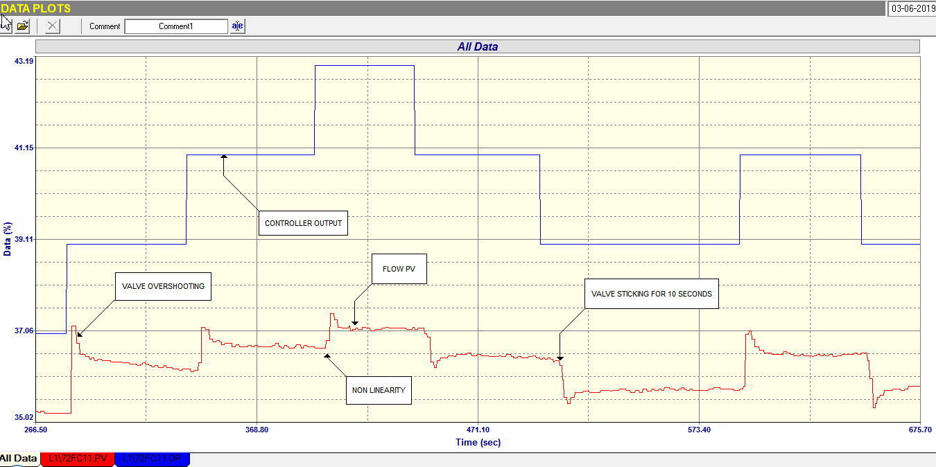
Figure 1.
In the example of the heater outlet temperature control loop discussed in this article, the first problem that was uncovered was that the cascade secondary flow loop had been configured with an algorithm that responded to setpoint changes with only an integral response. This resulted in terribly slow response to SP changes as there is no proportional action, and this is not good for cascade control where the secondary loop must respond as quickly as possible to follow setpoint changes as sent from the primary controller. The second problem was that the valve had some fairly serious issues. These are shown in Figure 1 which is an open loop test on the flow loop. The main trouble revealed in the test was that the valve was extremely sticky, in some cases taking many seconds for the positioner to pump enough air into the actuator to build up sufficient pressure to move the valve. Secondly the valve had fairly serious non-linear installed characteristics which can be seen from the differing size step responses of the PV to equally sized steps on the PD. This could mean that the speed of response to SP or load changes in automatic would differ as the PV moves around over the range. It could also result in instability at lower ranges if the tuning was too fast.
These valve problems meant that the flow controller’s tuning would have to be considerably slowed down to avoid instability, unless the valve could be fixed, which was not possible at the time due to production requirements. A new slower but stable tuning was then tried and a final closed loop test (not shown here) proved that the control was reasonable even though not fast.
The next tests were done on the primary temperature control loop. The first thing that was found from a closed loop “as found” test using the existing tuning in the temperature controller, but now using the correctly configured and properly tuned secondary flow loop, was that the control was unstable because of a far too fast integral term in the controller.
An open loop test was then performed to establish the dynamics of the temperature process so that scientific tuning could be calculated. When performing this test on a primary cascade loop, one normally only needs make one step up, and then one down again if time permits, as opposed to the multiple steps usually done for self-regulating processes. The reason for this is that the multiple steps are performed to trouble shoot problems with the final control element. However with cascade control, the secondary loop around the final control element is there to eliminate all the problems, so one can get away with only one step.
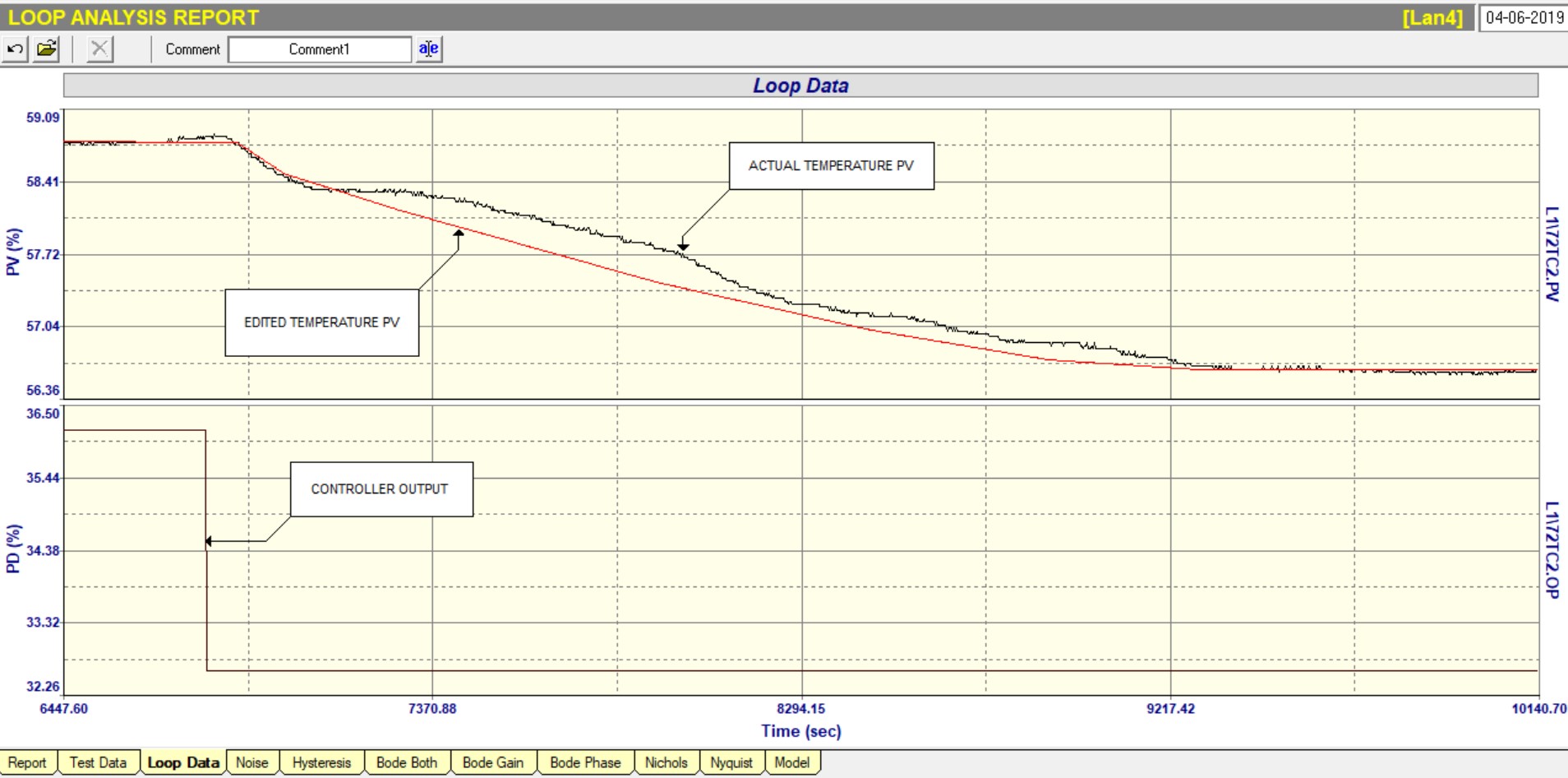
Figure 2.
The test took approximately 5 hours, as the temperature was very slow. Figure 2 shows a portion of the whole test and is the step bringing the temperature down. As one can generally not make too big a change on this type of temperature process, the actual PV response appears to be rather “wavy” which is caused by liitle disturbances occurring in the process. Therefore to establish the dynamics correctly one needs to draw in a line that smoothes out the variations, and this is shown in the figure as an “edited PV”. The edited curve is used for the tuning. The resultant model of the process showed that it was a very simple self-regulating process with a gain, a deadtime, and a first-order lag. The lag’s time constant turned out to be 16 minutes. The deadtime was negligible in comparison, which means that good control could be easily achieved. (Deadtime dominant processes where the deadtime is larger than the lag are regarded as difficult to control).
The slow temperature also meant that the secondary flow control loop was fine with its own slower tuning as it still responded extremely quickly compared to the temperature process, and thus could still allow good control of the temperature.
The new tuning was inserted, and the control then worked extremely well. The operators were delighted. A big problem had been “lifted off their backs”.
Figure 3.
Figure 3 shows a long term trend of the temperature loop running in automatic over a 16 hour period. The SP of the temperature was coming from an advanced control system, and it can be seen how closely the temperature PV followed it in spite of some fairly large load changes occurring from time to time. (These can be seen where the PD moves a lot which indicates the controller working well to deal with the PV movements caused by the disturbances).
Another wonderful example of the power of cascade control even with a really bad control element.