Home About us Contact us Protuner Loop Analyser & Tuner Educational PDFs Loop Signatures Case Histories
Michael Brown Control Engineering CC
Practical Process Control Training & Loop Optimisation
CASE HISTORY 184
WHY COULDN’T THEY TUNE THE LOOPS TO GET GOOD CONTROL?
I never get tired of showing people how important it is to trouble-shoot a loop before trying to tune, as so many people think tuning will overcome all problems in a control loop. Today’s article shows two examples where all the tuning in the world would not have attained good control.
In the first example, the operators in a petro-chemical refinery were having trouble trying to control the flow of a light end product, and had resorted to trying to run the loop in manual. However from time to time there were quite a few load disturbances which affected the flow badly, and they had to frequently revisit the loop to make adjustments.
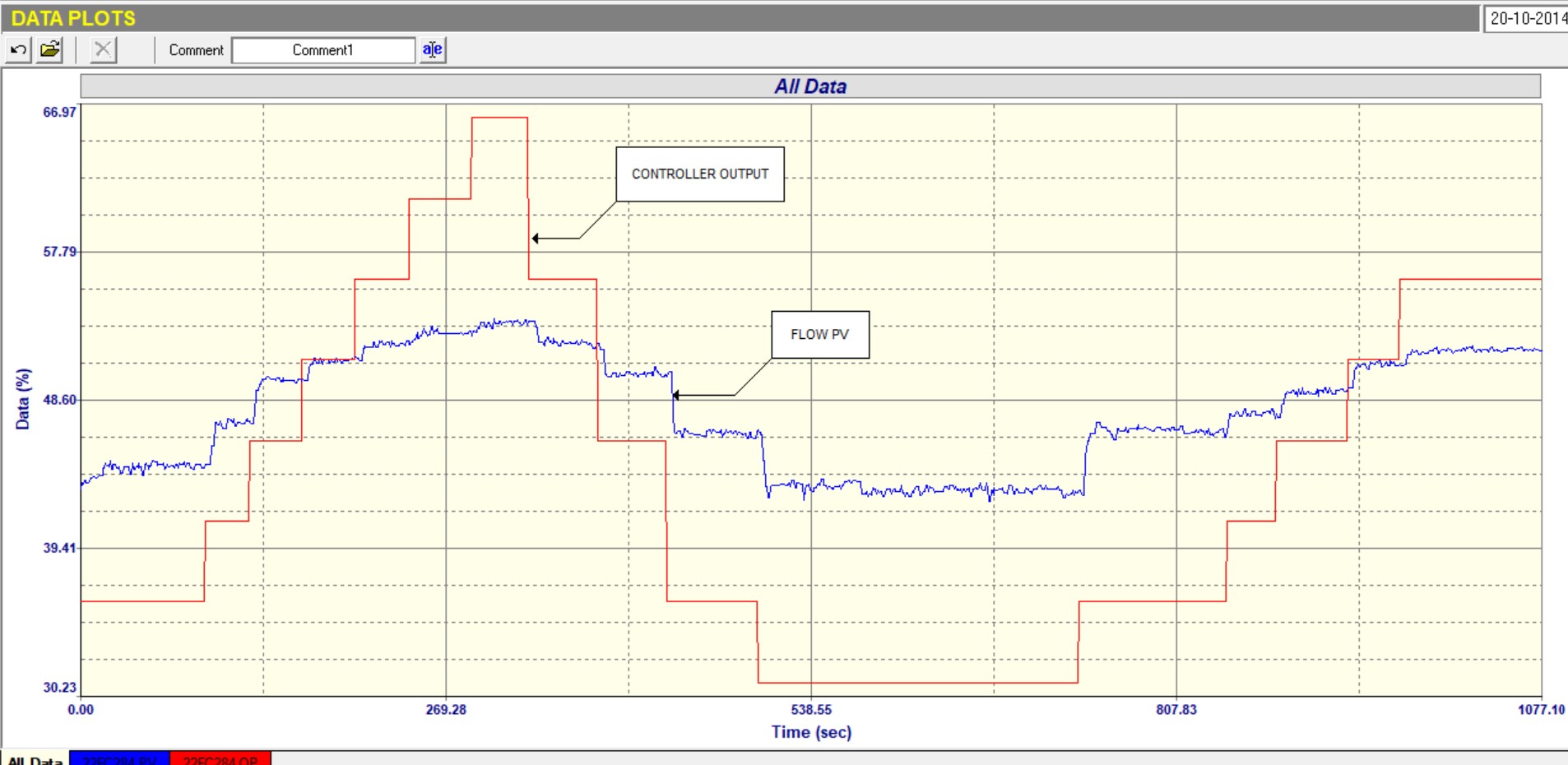
Figure 1 is a closed loop test “as found” (i.e. with the original tuning in it).
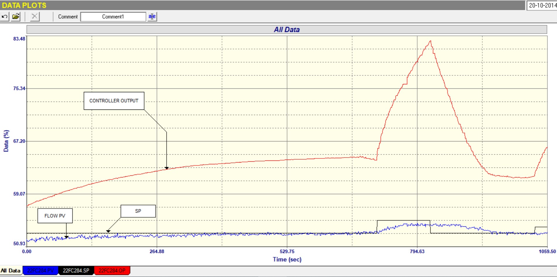
Figure 1.
At the start of the test one can see that the PV is slowly drifting up to SP and after about 10 minutes finally reaches it. The SP was then stepped up by a small 2%. The PV moved up but then seemed to settle out before reaching the SP. The PD (controller output) had moved up by about 20%, and was still rising quite steeply when the SP was stepped down by 2% again. The PD came down very quickly but it took the PV quite a while before it too started moving down. This is a sign of the valve not moving and is a sign that there is hysteresis or stickiness in the valve. The PV finally got back down to the SP with the PD well below the value it had been at the start of the step-up in SP. This would confirm that there is probably bad hysteresis in the valve.
The open loop test is shown in Figure 2, and the following can be seen in it:
Figure 2.
a) When the PD is below about 40% , the PV responds well to steps in the PD. When the PD is above that the steps in PV are very much smaller, and got smaller the higher the PD was stepped. Although there is a chance that there is something strange with the installed characteristics of the valve it is far more likely that the flow is reaching a saturation, probably due to insufficient pressure in the pipe.
b) The process gain of the loop is about 0.5 - based on the lowest step changes. This is usually a sign that the flow transmitter has too wide a span, but this might not be the case if the flow could have reacted better if there was more pressure in the pipe.
c) There is no real indication in this test of valve hysteresis or stickiness, but it must be realised that these things don’t always show when a valve is reacting to step changes of PD.
A final closed loop test was carried out with improved tuning and this is shown in Figure 3. It can be seen that the valve was extremely sticky in fact and taking a long time to react to many of the SP changes.
Unfortunately the plant needed to keep the SP at around 50%, where it was in the saturation region, and this is a case where the plant needed to try and increase the pressure to get the flow to react properly, and also the valve needed servicing. Only then would they be able to attain good control.
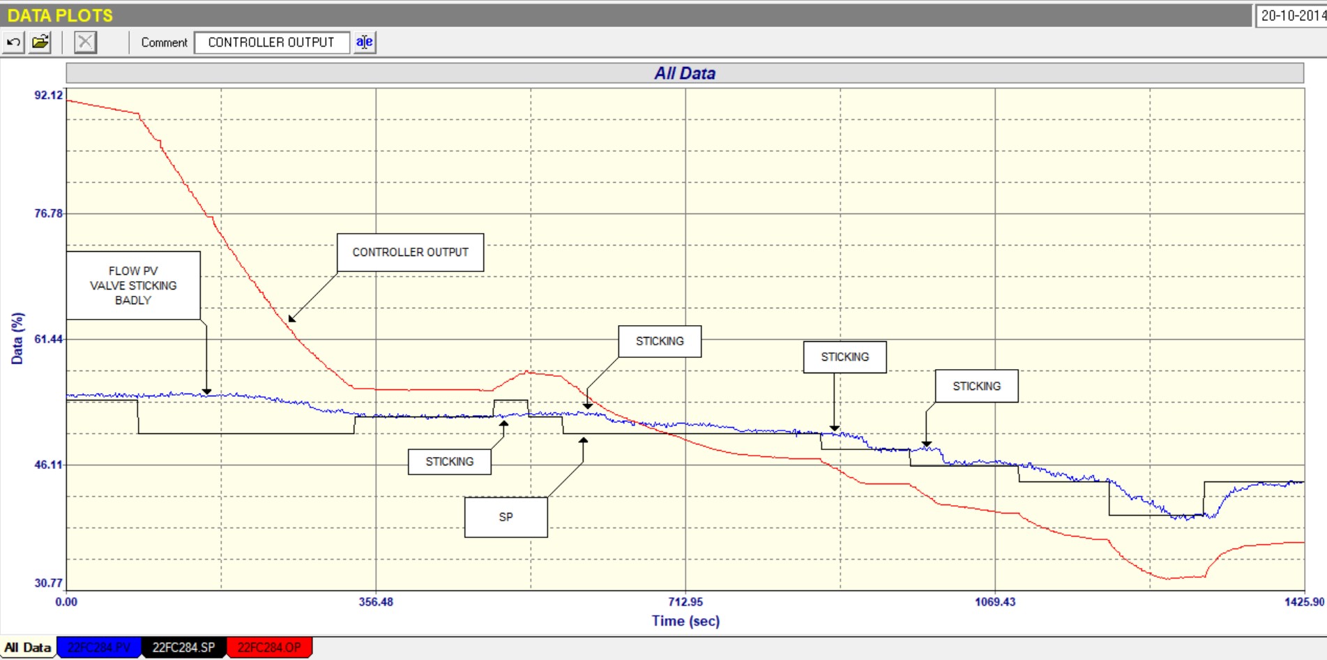
Figure 3.
The second example is even more dramatic. The loop was to control the flow of waste gas to the flare in the same plant. This is quite an important control in such plants. The problem was that the flow followed setpoint but cycled quite wildly about it.
Figure 4 shows the closed loop “as found” test with changes in SP being made, and it can be seen how badly and frequently the rapid fluctuations occurred.
Many people in the C&I department had tried tuning the controller to stop the fluctuations, but all to no avail.
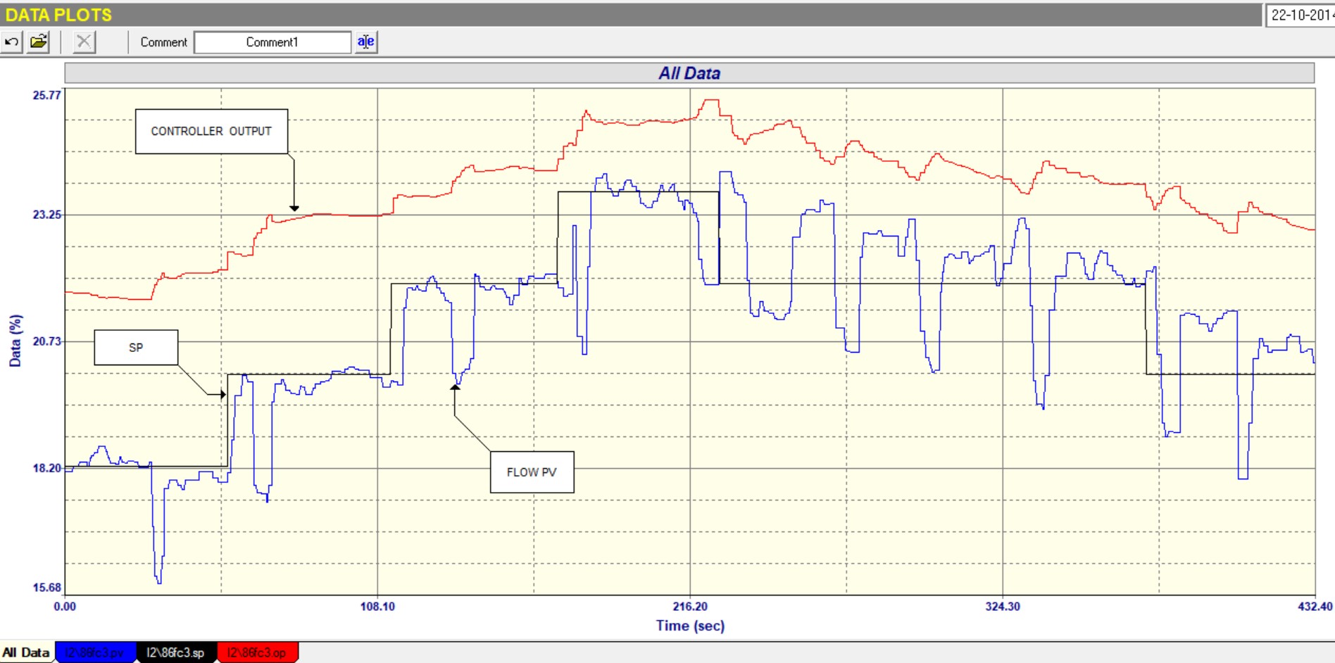
Figure 4.
Figure 5 is the open loop test which immediately showed what was happening. The valve was jumping around badly, and on changes in the PD signal gave huge over or undershoots. Sometimes it didn’t respond properly at all, sometimes it cycled, sometimes it moved the wrong way, sometimes it stuck, sometimes moved too much, all this making it very non-repeatable.
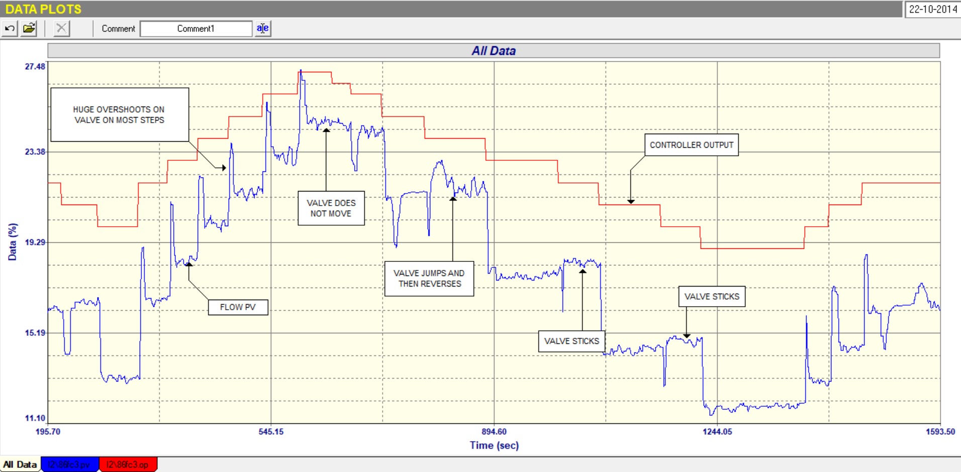
Figure 5.
This is one of the most interesting and dramatic examples I have seen of a valve not following the PD signal properly. Luckily the fluctuations were all in a relatively narrow band, so an average flow control was possible. Another interesting thing is that nobody in the C&I department were aware of the problem, and all had tried tuning.
The actual problems later found with the valve was that firstly there was some very bad play in loose linkages, and also that the positioner had not been properly tuned.