Home About us Contact us Protuner Loop Analyser & Tuner Educational PDFs Loop Signatures Case Histories
Michael Brown Control Engineering CC
Practical Process Control Training & Loop Optimisation
CASE HISTORY 186
DON’T ALWAYS TRUST VALVE POSITION FEEDBACK SIGNALS
I recently encountered an interesting problem in a minerals recovery processing plant. The loop in question was a gas flow control to a burner and was considered very important for the process temperature control. The operators reported that the loop cycled badly in automatic and was very difficult to control manually. The C&I technicians had tried all sorts of tunings without any improvement.
They included this loop in a series of optimisation tests we were doing as part of the practical we held after they had finished the classroom part of my basic control course. They said they knew that valve problems often cause problems for control but that this loop had a valve position feedback signal on it and the feedback signal closely followed the controller output signal so they were pretty sure it wasn’t the cause of the problem.
The first test we normally carry out is a “Closed Loop As Found” test where we recorded how the loop responded to SP (setpoint) changes in automatic with the original existing tuning parameters. However as reported the loop cycled badly.
The second test was an Open Loop test where the controller is placed in manual, and various steps are then made on the PD (controller output). Part of this test is shown in Figure 1. (Unfortunately we did not record the valve position feedback signal). It can be immediately seen that there was in fact a huge valve problem as the valve was not only apparently “sticking” in places but also had huge “almost hysteresis” of over 10%. I say “almost hysteresis” because it did move a little on most reversals and then stuck whilst the PD had to move a further 10% before the valve moved again. This was the major reason for the cycling.
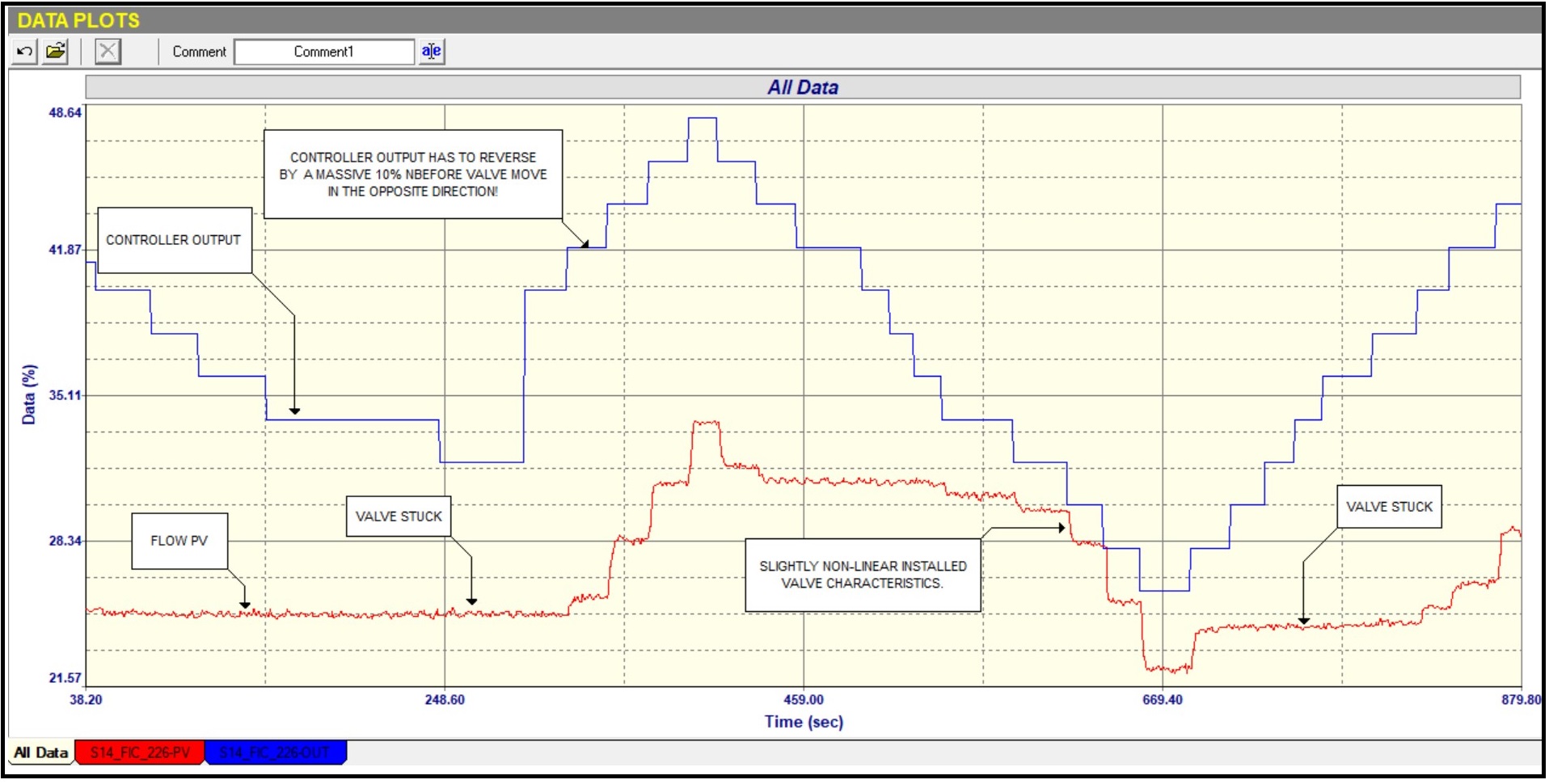
Figure 1.
The question is as to why the valve feedback signal followed the PD so closely? The answer is, and this is something every control practitioner should be aware of, is that valve position feedback signals generally do not track the actual valve position, but track the position of the actuator. Now depending on the type of valve and actuator there are often various linkages joining the two. In this case the valve was a butterfly valve which is a rotary valve. The actuator was a spring and diaphragm type which has a linear action. To convert the linear action to a rotary action, manufacturers employ various techniques, typically gear-trains. Therefore the hysteresis and/or apparent stickiness may actually be due to play in the linkages.
On the steps where the valve and hence the flow PV did follow the PD we were able to see that there was a slight non-linear installed characteristic in the valve, and we were able to establish the process dynamics to allow us to get good tuning parameters. (The original tuning parameters were actually too fast and were contributing to the cycling so it wasn’t only due to the valve problem, and the tuning was also causing instability).
Part of the “Final Closed Loop” test with the new parameters is shown in Figure 2 and is interesting. On the SP step down it can be seen how the valve started moving and then “stuck”, and the PD then integrated down well over 10% before the valve could move again and bring the PV back to SP. On the SP step up the valve initially didn’t move at all until the PD had integrated up the same amount and then it moved to get the PV to SP.
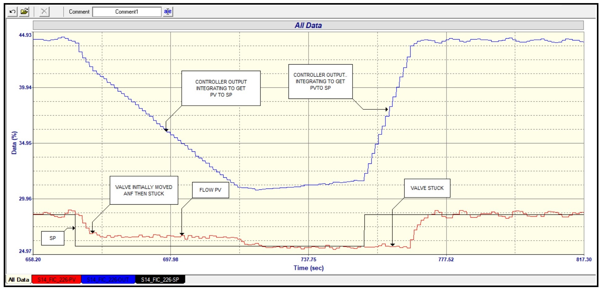
Figure 2.
This is another example of how important it is to analyse a loop before tuning and to be aware of the various problems that can exist. As I have said many times in the past that the old adage that tuning can solve all problems is nonsense.
I have seen the same problem of slippage in the valve linkages many times in the past, and it something that not many C&I practitioners seem to be aware of.