Home About us Contact us Protuner Loop Analyser & Tuner Educational PDFs Loop Signatures Case Histories
Michael Brown Control Engineering CC
Practical Process Control Training & Loop Optimisation
CASE HISTORY189
POOR FURNACE TEMPERATURE CONTROL
Many process engineers do not appreciate the importance of flow loops in their unit controls. A senior process engineer once told me that flow loops need not be tuned well as they generally have little effect on the more important and much slower loops like temperatures and pressures. In actual fact flow loops can be vitally important for ensuring that other controls work properly. The example given here is an excellent illustration of this.
The process unit used for this example is the steam desuperheater on a boiler in a petro-chemical refinery. The water is heated using gas as the fuel. The final desuperheater outlet temperature is a cascade secondary loop with the primary control being the outlet temperature control of the upstream desuperheater. (Just out of interest, there was a measurement of the outlet steam flow after the second desuperheater, but they had not used this as a further cascade to ensure the temperature control worked properly, which is something I recommended they do. A secondary flow cascade loop takes care of any valve problems as it would have quickly ensured that the flow of steam keeps to the amount demanded by the temperature controller. In actual fact there were several problems with steam desuperheater valve, and this may be used for a future article.)
The problem being experienced on the steam temperature was that it was cycling quite badly, and they had not been able to establish the cause.
Investigations were carried out as to what was causing the cycle by checking all the various controls that could have an effect on the desuperheaters outlet temperatures. It was found quite quickly that the culprit causing the problem was the combustion air flow control loop.
Figure 1.
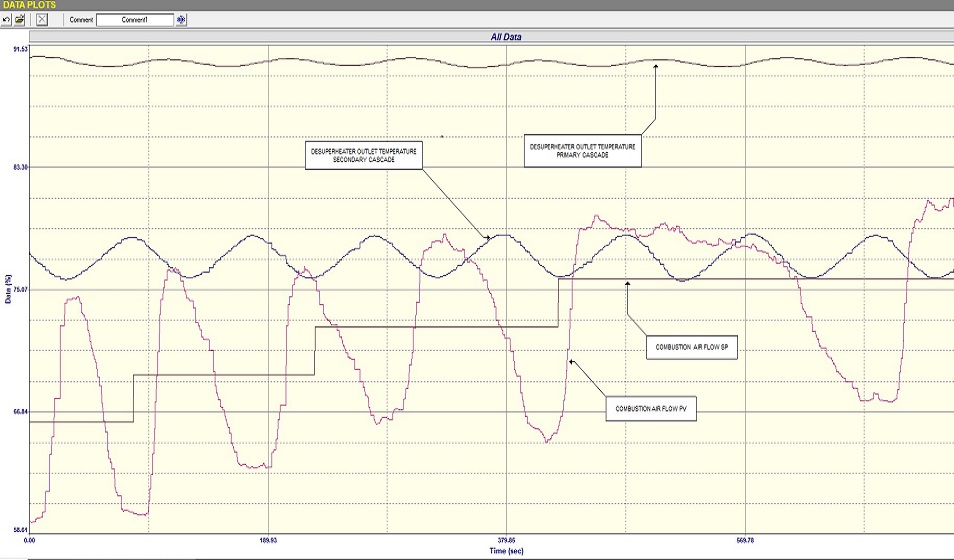
Figure 1 is a “Closed Loop as Found” test on the airflow with the controller in automatic and using the original tuning parameters. A series of setpoint changes was made as can be seen in the figure. It can be seen that the flow was apparently in a continuous slow cycle with a 20% amplitude and a period of roughly 100 seconds. The other 2 traces shown in the figure are the outlet temperatures of the two desuperheaters in cascade. It can be clearly seen what a large influence the cycle of the air flow was having on them, particularly on the secondary cascade desuperheater.
Figure 2.
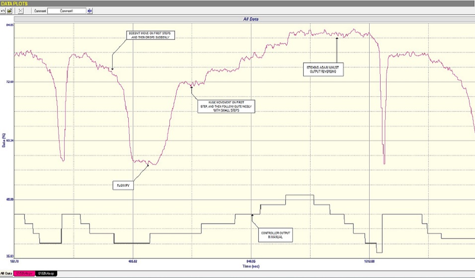
• The moment the PD dropped below 41% the flow immediately dropped by about 20%, and one could not control the flow once the Pd had gone below that value.
• When the PD was moved up in small 3% steps from 41%, the flow responded pretty well. However when we stepped the PD down again the flow did not move at all until the PD went below 41%. Then it immediately dropped by the 20% as mentioned above.
• When repeating the test it was found on a couple occasions that the flow did occasionally slowly move a little on downward steps of the PD in the upper region.
These observations show that there were very serious problems with the air damper, and proved that no real control was possible until it could be fixed or replaced. It also conclusively showed why the cycle occurred in automatic, with the controller trying to get the flow to a value in the region over which the valve just jumped up and down.
This is a good example of how a poor control on a flow can seriously influence other more important and slower controls.