Home About us Contact us Protuner Loop Analyser & Tuner Educational PDFs Loop Signatures Case Histories
Michael Brown Control Engineering CC
Practical Process Control Training & Loop Optimisation
Control Loop Case History 58
Problems in an interactive combustion oil control system
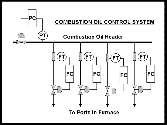
The author was recently requested to investigate the control system for the combustion oil feed to a furnace used in a manufacturing process. Oil is fed into the furnace through various ports and the flow through each port is individually adjusted via the setpoint on its controller. A schematic of the system showing a few of the oil feeds is given in Figure 1.
Figure 1
The oil feeds are alternated approximately every 20 minutes between the opposite sides of the furnace to avoid overheating of the furnace walls. The flow controls are extremely important to keep temperature in the furnace constant at the required temperature.
The system is inherently highly interactive. A change in the pressure will affect the flows, and a change in an individual flow will affect the pressure in the header and hence all the other flows.
There are only 2 ways to deal with interactive feedback systems. The first way is to try and tune the individual loops in the system to have minimum effect on each other, and the other way is to use decoupling (or multivariable control). The latter method in essence employs multiple feedforward controls to decouple the individual loops from each other. This is generally not an option due to complexity and expense on a system such as this.
Decoupling by tuning entails tuning the loops to react at different speeds. Therefore one generally tries to tune the more important loops fast and the less important slowly. In this case the flows are important. However due to the fact that there are multiple flows, which will all be directly affected by changes in pressure, it becomes obvious that the pressure control is really vital, and if it can react to changes as fast as possible to keep the pressure as constant as possible, then there is a much better chance of being able to obtain overall good flow control on the individual flow loops. Also due to the fact that the individual flows are small in comparison with the total flow passing through the pressure control valve, the individual flows will have a much smaller interactive effect on the pressure than the pressure will have on them. Therefore the way that one would go about tuning a system like this is to tune the pressure controller fast and the individual flow controllers slower.
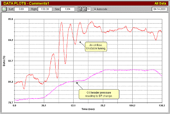
Figure 2 shows part of the initial closed loop "as found" test on the system.
Figure 2
Only 2 traces are shown here, one being the oil header pressure, and the other being one of the individual flows. A setpoint change has been made on the pressure controller. It can be seen that the pressure is tuned slowly and is reacting slowly, but the flow has been tuned extremely fast and is very cyclic, in fact almost unstable. This is completely the wrong way round. The test also shows how important the pressure control is, as it has a direct and marked effect on the flow.
As mentioned many times in these articles, most people mistakenly confuse optimisation of control loops with tuning. Tuning is the generally the last process involved in optimisation. Generally tuning blindly is useless, and is probably successful only about 25% of the time. Proper optimisation examines all aspects of the system, the individual loops, and the problems associated with their internal components, and also involves gaining a full understanding of all these points and of the requirements of the control. To this end, one performs all sorts of tests and examinations before actually performing the tuning.
This is well illustrated in this case as many problems were found in the individual loops making up the system. A few of these will be shown here.
The first case was in the pressure control loop which as mentioned above is critically important for the success of the whole oil feed system.
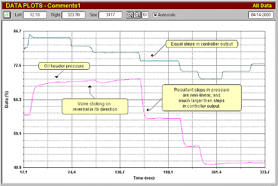
Figure 3 illustrates an open loop test on the pressure, where the controller is in manual and step-changes are being made in output.
Figure 3
It can be seen from the figure that the there are major problems associated with the control valve, which will mitigate against good control.
Firstly the size of the changes in the pressure resulting from the changes being made in the controller output are about 5 times larger than the size of the controller output changes. This means that the valve is about 5 times oversized. Previous articles have detailed the problems associated with oversized valves, but in essence the quality of control is roughly degraded directly proportional to the amount of oversizing. The ratio of the size of the steps is known as the process gain or open loop gain ((PV/(PD).
Secondly one can see that the valve does not move immediately on a reversal in the controller output signal, and in fact the output has to move over 5% in a reverse direction, before the valve starts moving. This is generally referred to as "valve hysteresis" which in actuality is the combined effect of both true hysteresis incurred by static friction on the valve stem, and deadband in the valve linkages. The overall effect of hysteresis is to slow down the control quite substantially, which again adversely affects the control variance.
Thirdly although the steps made in the controller output are all equal, the size of the resultant steps in the controller output are not. This is due to an incorrect inherent valve characteristic causing a non-linear installed characteristic. This effectively means that the process gain changes as the process variable moves over the measuring range. Thus as the proportional gain in a controller must be set to take the process gain into account, the tuning can be correct at only one point in the measuring range.
On a process as important as this, where the flows can only be as good as the pressure control, it is vital that all these points be corrected before better control can be obtained.
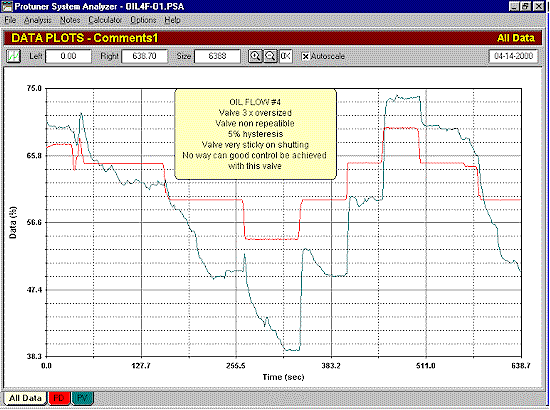
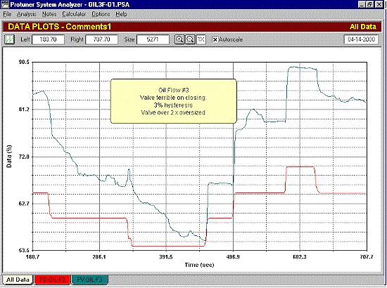
Tests on the flow loops also revealed that most of the valves are in a very sorry state. Figures 4 and 5 show tests on oil flow loop 4 and 5 respectively. In both of these tests one can see that the valves can open quickly , but are terribly sluggish on closing. Both are oversized, and suffer from bad hysteresis. (As a general rule, the maximum acceptable hysteresis on a valve with positioner is 1%).
Figure 4
Figure 5
The actual tuning of all the loops was also way out. Bearing in mind that the tunings will have to be recalculated once the valves are sorted out, and tuning the pressure fast, and the flows relatively slowly, the tunings calculated on the existing dynamics were:
Pressure Control
The as found tuning was:
P=100%,
I=100 seconds/repeat
D=1 second
In addition there was a 1 second filter in the controller and a 9.6 second filter on the transmitter.
Much has been said about unnecessary filtering in previous articles, and this is another example of lack of understanding of filtering. There is certainly no need for any filters on this remarkably clean and noise free signal as can be seen in Figure 3. In addition, the ridiculously large integral used in the controller on a process with such a fast response means that there is no way the control can deal speedily with slow and smallish load changes. It really is extremely bad tuning.
The desired tuning as calculated by the Protuner loop analyser and taking into account the large hysteresis, is as follows. (One tries to use a tuning with minimal overshoot on loops with unacceptable valve hysteresis to avoid unnecessary reversing of the valve, because every time the valve has to be reversed, the controller output has to move through the hysteresis band before the valve starts moving in the opposite direction).
P=1,300%,
I=2.1 seconds/repeat
No D term or filtering is required.
Unfortunately another adverse effect of oversized valves is that the gain in the controller must be reduced proportionally, and many controllers on the market cut off their low end gain at about 0.1 or 1000% proportional band. This was the case with the controllers in use in this plant, so the biggest proportional band that could be inserted in the controller was 999%. This is a little too cyclic for this application, but it had to do.
Flow Controls
The following settings are typical of those inserted in most of the oil flow controllers in the system.
The as found tuning was:
P=80%,
I=14 seconds/repeat
In addition there was a 1 second filter in the controller and a 9.6 second filter on the transmitter.
Again with the oversized and hysteresis plagued valves, the best tuning that could be used was:
P=999%,
I=1.3 seconds/repeat
No filtering is required.
One would like to have made the proportional band considerably bigger to slow the tuning down in view of the interaction, but again this was prevented by the limited proportional band range in the controller.
