Home About us Contact us Protuner Loop Analyser & Tuner Educational PDFs Loop Signatures Case Histories
Michael Brown Control Engineering CC
Practical Process Control Training & Loop Optimisation
Control Loop Case History 59
The regulatory controls in most plants do not work properly
As mentioned many times in previous articles, most people's perceptions are that the basic regulatory controls are operating reasonably well in their plants. Our experience has proved time and time again that in probably well over 95% of all plants the basic regulatory controls are completely inefficient in automatic. Working in various plants over the last few months I have had numerous further examples of this which are worth relating. A few of these are given below:
Case 1: A simple flow loop on a mine
After looking at several loops on a mine in Namibia, all of which displayed horrific problems, the chief instrumentation technician with relief finally found a flow loop which he believed was really operating well. The loop was a simple flow control. The screen on the SCADA system showed the loop running in automatic with the process variable sitting on top of the setpoint. The process was running under stable conditions with no load variations taking place. It certainly did look good.
I asked him for the tuning parameters. These were P = 0.95 (gain), and I = 20 sec./repeat.
These are certainly not good for a flow control, so I asked him to make a 5% step setpoint change. The loop went completely unstable, and the smile was wiped from the technician's face.
Why did this happen? Why was the loop not cycling previously?
The answer lies in the fact that as in most plants, the tuning is way out. Loops are mostly completely detuned, but in a few cases like this one, they are tuned unstable. In either case because the tuning is unsatisfactory, the operators make changes in manual, and only put the controller back into automatic when everything has reached steady state. If nothing further disturbs the loop, it stays where it is, looking good, but in actuality being completely incapable of dealing with setpoint or load changes.
Case 2: Problems controlling with overspanned magnetic transmitter.
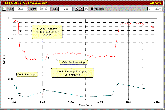
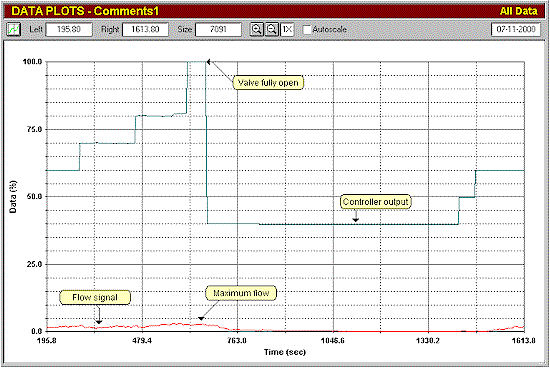
A rather important pulp flow loop on a paper machine was investigated. Everyone assumed its operation was satisfactory. An open loop test was performed (see Figure 1).
Figure 1
The test revealed the amazing fact that the control was in reality not operating at all.
The normal pulp flow required was 70 l/m. As can be seen in Figure 1, once the Protuner analyser was connected to the loop, it was found that this flow was almost at the bottom end of the range. The flowmeter calibration was checked, and it was found that it was set to 0-6,600 l/m. This means that the plant was trying to control the process at only 1% of the measuring range. In general a magnetic flowmeter is only really accurate over a 10:1 turn-down. The readings were really pretty meaningless.
Figure 1 also reveals that there appears to be a problem with the valve stroking, as the flow only starts once the controller output reaches 50%.
It was suggested to the client that the magnetic flowmeter be rescaled, and the valve be restroked, before any further optimisation work be undertaken.
Case 3: An important loop everyone was happy with.
Pulp consistency is a critical factor in paper making. Very, very roughly, it could be described as the density of the pulp, and is controlled by water addition. Good consistency control is most important for good and profitable paper manufacturing.
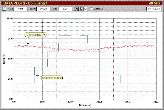
Figure 2 shows an open loop test on a pulp consistency loop in a large paper plant.
Figure 2
Prior to the test everyone in the plant apparently were not really aware that the loop had a problem. However the process never ran at setpoint. The test showed that there was a major problem in either the measurement or design of the loop. Moving the controller output over 80% resulted in a change of consistency of only 7%!
The whole engineering of the process needed investigating.
Case 4: Problems on a pulp flow with oversized valve.
One of the important processes in paper making is the blending of the various pulps. The flow of each constituent is controlled from a master controller through a ratio cascade system. It is extremely important to control the individual flows accurately and quickly to catch any change, and keep the blend the same under all conditions.
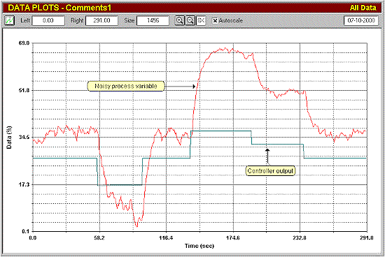
Figure 3 shows an open loop test on a recycled fibre flow being mixed into the blend.
Figure 3
The test shows that there is a very high noise content on the flow and that the response to a step change on the controller output shows a lag of approximately 6 seconds. The noise in fact was being caused by the incorrect use of an older model DC excited magnetic flowmeter which could not cope with the solid contents in pulp flows, and the lag was caused by relatively large damping in the flowmeter, which was inserted in order to try and deal with the noise. In addition, the process gain is 3.5 which indicates the valve is approximately three and a half time oversized. (See our article Loop Signature 3, for definition of process gain, and explanation of problems with oversized valves).
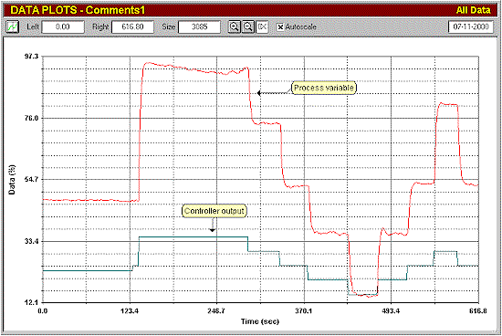
The converter on the flowmeter was changed out for a new model which could cope with pulp flows. The new open loop test is shown in Figure 4.
Figure 4
The signal is now relatively noise free and the response to the flow much quicker. Without the noise it can be seen that the process gain is actually closer to 5. A five times oversized valve is not good for control.
Figure 5, a closed loop final test, shows the response to step changes is setpoint with good tuning.
Figure 5
The test shows that a 3% amplitude slip-stick cycle is taking place. Slip-stick cycles have been described in previous articles, and will also be dealt with again in a future Loop Signature. They occur on approximately 15% of all well tuned fast self-regulating loops. In this case, if the valve had been properly sized, the amplitude of the cycle would have been much smaller, and therefore relatively insignificant.
Once again prior to these tests, everyone in the plant had been happy with the performance of the loop.
It is interesting to speculate what improvements in quality, savings in costs, and increase in productivity, could be obtained in plants producing products like paper with critically important processes, if people were really aware of what was happening in their base layer controls and optimised them properly.
