Home About us Contact us Protuner Loop Analyser & Tuner Educational PDFs Loop Signatures Case Histories
Michael Brown Control Engineering CC
Practical Process Control Training & Loop Optimisation
LOOP SIGNATURE 17
CASCADE CONTROL
HOW TO MAKE A BAD VALVE INTO A GOOD VALVE
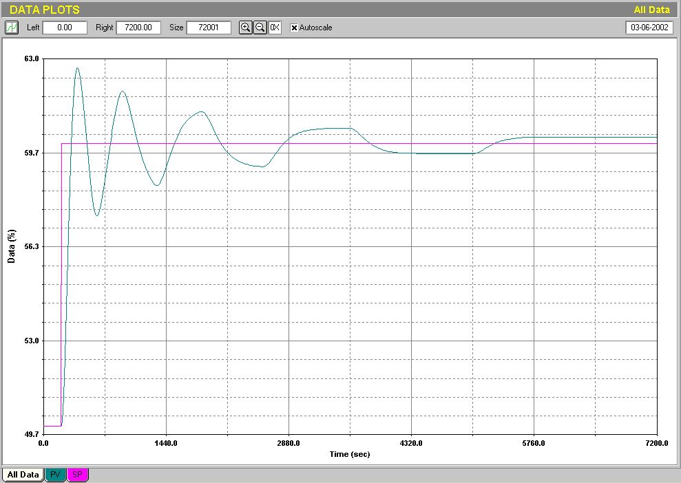
People often have little realisation as to how badly a faulty valve can affect the performance of the control of the loop. Figure 1 shows the response of a slow temperature control loop to a setpoint change. In the test taken over nearly two hours the loop has not still stopped cycling. It looks like it has been terribly badly tuned. However, at the time of this test it was determined that the control valve suffered from a hysteresis of 6.8%, which is extremely bad (see earlier loop signature articles dealing with hysteresis).
Fig 1.
This is an incredibly good example of why one cannot afford to use bad valves on slow processes. Figure 3 shows a heat exchanger being controlled by a single temperature controller. The temperature of the process fluid is the input to the controller, and the controller's output is fed directly to the steam valve.
Fig. 3
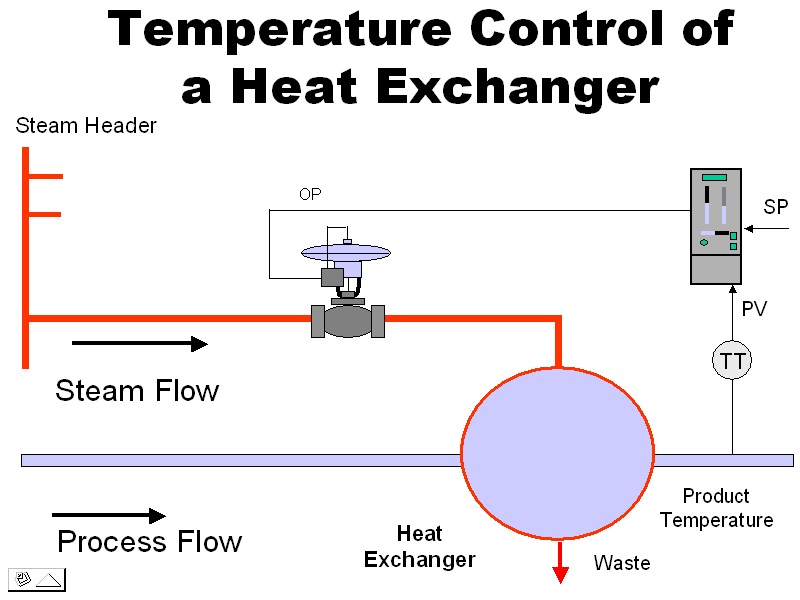
This method of control is not an ideal way of controlling any slow process, and is particularly bad in the case of a heat exchanger. There are two reasons for this. Firstly any slow process like this exchanger can only be tuned very slowly, because when tuning self-regulating processes one generally sets the integral term in the controller close to the dominant time constant of the process. This often means integral times of many minutes per repeat.
With slow settings like this, the controller can only make slow corrections if any load disturbances arise. In the case of the heat exchanger under discussion, the steam is fed from a header that has other take-offs leading from it. This can result in fluctuations of pressure in the header. If for example the header steam pressure suddenly dropped by 3% as steam was suddenly drawn off to another process, the steam flow to the exchanger would be reduced. The controlled temperature would then slowly start to drop. The controller with its slow integral would take a long time to catch and correct this, and large control variance would result.
Secondly, any valve problems like hysteresis cause havoc in slow control loops with long integral settings, as can be seen in Figure 1, and as discussed in the previous articles.
Now what one must realise is that the output of a controller sets the position of the valve stem. If the valve was perfect without hysteresis, had linear installed characteristics, and there was constant pressure conditions in its feed line, then this would result in achieving the correct amount of flow through the valve to satisfy the dictates of the controller. In reality, valves are seldom perfect and there is no guarantee that the stem will move to the position as dictated by the controller (particularly with hysteresis in the valve). Secondly it may not have completely linear installed characteristics, and thirdly if pressure variations in the line can occur (as in this case), then the correct flow of flow through the valve will definitely not be obtained.
If it were possible to ensure that the correct flow rate did follow the controller's output, as would happen if we had a perfect valve, then the problems would be overcome. So how then can one make a real valve complete with problems into a perfect valve?
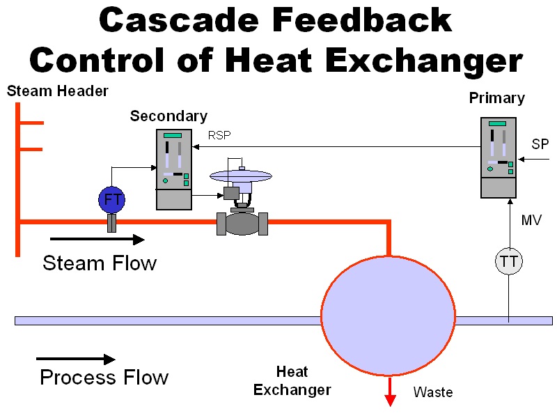
The answer is very simple. One makes use of a technique called cascade control whereby a second controller is used to control the flow of fluid through the valve. (This obviously also involves having to install a flowmeter in the steam line). This new configuration is shown in Figure 4.
Flow controllers are tuned with parameters that are lightning fast as compared with those in the temperature controller. The time constant of a flow loop is in the order of 1 or 2 seconds, which is what the integral will be set at in the flow controller. This means that the flow controller is quite capable of correcting for problems like line pressure variations, non-linearity, and hysteresis in the valve relatively quickly. Thus the temperature process will not be affected by these problems as it was prior to installation of the cascade secondary. Even if the flow loop suffers from bad phenomena like stick-slip cycling and hysteresis, the average flow through the valve will probably be more than good enough to keep the temperature on setpoint.
Fig. 4
Cascade control can really work brilliantly, even as mentioned above, with relatively poor valves. As discussed, it effectively takes the valve problems (as well as variations in pressure in the valve line) out of the equation, and in fact could be said to have made a bad valve into a good one.
I believe that cascade control is really mandatory for any critical slow control process in a plant. I have often persuaded plants to install cascade systems on important slow loops with absolutely excellent results, and has resulted in vastly improved control performance and decreased variance.
Cascade systems are typically found in the following combinations:
Primary Slave
Temperature Flow
Temperature Pressure
Level Flow
Controller Valve positioner
Temperature Temperature
Sometimes people get very confused about the purpose of cascade control, and I have often heard process operators expressing the opinion that it is stupid having two controllers to control only one valve. Confusion also often reigns when it comes to a level control with a cascaded flow control on the valve. Many plant personnel believe the level controller is there to keep the level constant, and the flow controller is there to keep the flow constant. Unfortunately the second law of control states that you can only control as many variables as you have valves, so it doesn't work that way. I often have quite a job explaining that the only reason for the flow control is to ensure that the valve does its job correctly. In passing I would mention that this combination is particularly effective as level is an integrating process, which is very likely to cycle continuously with any hysteresis in the valve. Control will also be adversely affected with any non-linearity in the valve. Adding the flow loop now takes the valve out of the integrating loop and puts it into a self-regulating loop, which is faster, and subject to far less problems.
One very important point to remember is that cascade control can only work really well if the secondary process is ideally ten times faster than the primary process. Why? The reason is that cascade loops are interactive. If they both have similar response times they will tend to fight each other and could be very cyclic. A general rule of thumb is that if the secondary is less than about six times faster than the primary, then it may be better to dispense with the cascade entirely.
"The speed" of a process is best judged by the ultimate frequency of that process. (Note: The ultimate frequency is the frequency at which the loop oscillates when sufficient gain is inserted in the proportional only controller). Another and rougher method of judging speed, is by looking at the response time of the process to a step change on the input.
In conclusion I would urge people to try using cascade control on slow and important loops where performance is not as good as desired. The results will be very rewarding if the system is set up properly.